Understanding Residential Electrical Systems: Fundamentals, Color Codes, and Boxes
I’m Randy Harmuth, Master Electrician and owner of Harmony Electric serving Denver and surrounding communities. Finding a reliable home wiring guide or printable reference PDF is one of the best ways to understand your home’s circuits before tackling basic DIY repairs.
Practical wiring manuals provide clear visual schematics, color-coding rules, and step-by-step layout diagrams so you can plan projects and verify safety steps before picking up your tools.
To understand how home wiring works, it helps to think of electricity like water running through your home’s plumbing. Voltage acts like water pressure pushing through a pipe, while amperage represents the actual volume of current flowing through the wire.
In a standard residential split-phase electrical service, your utility company delivers 240 volts through three overhead or underground service lines. This feed consists of two separate 120-volt hot lines and one grounded neutral line.
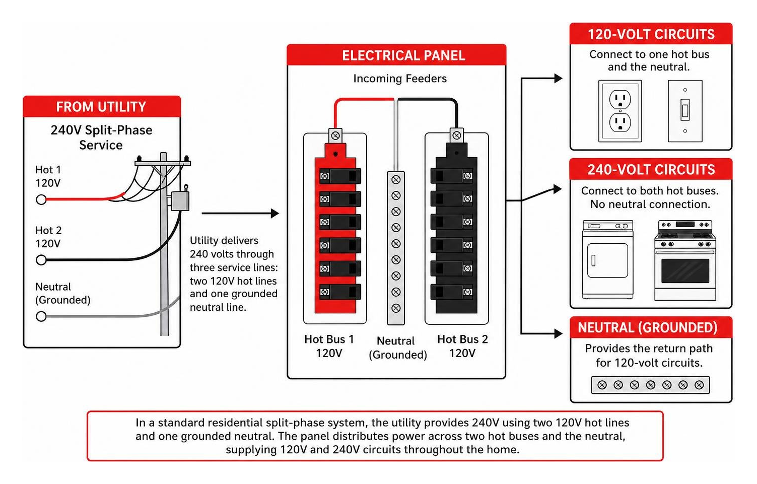
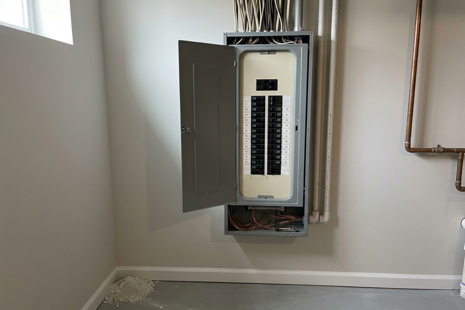
When you look inside electric panel complete guide references, you will see how these incoming feeders route power across two separate bus bars. A standard 120-volt household circuit connects to a single hot bus bar, while 240-volt heavy appliances tap into both hot bars simultaneously.
Before touching any project, learning the secret language of circuits: your guide to electrical symbols will help you read standard wiring blueprints without confusion.
Modern residential branch circuits rely on non-metallic sheathed cable (commonly called Romex or NM-B cable). The conductors inside the cable bundle perform distinct, critical jobs:
- Hot Conductors: Carry electrical current under continuous voltage from the breaker panel directly to your switches, receptacles, and light fixtures.
- Neutral Conductors: Provide the return pathway for current back to the panel under zero voltage during normal operation to complete the circuit loop.
- Ground Conductors: Act as an emergency safety return path, directing stray fault current safely into the earth if a loose wire contacts metal components.
Wire Color Codes and Terminal Screw Standards
In my years working on Denver homes, I’ve found that electrical safety depends entirely on consistent color coding across conductors and terminal connection points:
- Black Wires: Standard hot conductors carrying 120 volts of electricity.
- Red Wires: Secondary hot conductors used in 240-volt circuits or as traveler wires in multi-switch lighting runs.
- White Wires: Grounded neutral return conductors.
- Bare Copper or Green Wires: Equipment grounding conductors.
Connecting wires to wall devices requires matching conductor colors directly to terminal hardware:
- Brass Terminal Screws: Connect exclusively to hot conductors (black or red wires).
- Silver Terminal Screws: Connect exclusively to neutral conductors (white wires).
- Green Hex Screws: Connect exclusively to bare copper or green grounding wires.
When using a white conductor as a switch leg or hot traveler in a multi-way switch setup, we always re-identify that conductor in the field. Wrapping black electrical tape securely around both ends of the white wire insulation signals that it carries live voltage.
Metal Boxes vs. Plastic Boxes
The material of your wall box determines how equipment grounding connections are handled.
Metal electrical boxes conduct electricity. Because of this, the bare copper ground wire attaches directly to the metal box frame using a dedicated green grounding screw or approved grounding clip. A separate copper pigtail wire then connects from the box frame to the receptacle or switch grounding terminal.
Non-metallic (PVC or fiberglass) boxes do not conduct electricity. When using plastic boxes, the ground wire bypasses the box entirely and attaches straight to the green grounding screw on the electrical device.
| Box Feature | Metal Electrical Boxes | Non-Metallic (Plastic/PVC) Boxes |
|---|---|---|
| Material Conductivity | Conductive metal | Non-conductive polymer |
| Grounding Requirement | Box must be grounded via screw/clip | Ground attaches directly to device |
| Cable Clamping | Requires internal or external clamps | Features integrated friction entry tabs |
| Common Application | Exposed conduit, basements, garages | Standard finished residential drywall |
| Box Fill Handling | Standard metal volume ratings | Stamped interior cubic-inch ratings |
Every electrical box has a strict physical capacity known as box fill. Overcrowding wires inside an undersized box creates heat buildup and risks damaged insulation.
To determine box fill volume, count all hot and neutral conductors as one unit each based on wire size. All internal cable clamps count as one unit combined, each installed device (switch or outlet) counts as two units, and all grounding conductors entering the box count collectively as a single unit.
Finding and Using the Complete Guide to Home Wiring PDF Free Download
Digital wiring manuals and printable PDFs offer useful visual references when planning basic home electrical projects. Many homeowners turn to online libraries and reference guides to find digital copies of classic instructional books.
Where to Access Home Wiring Reference Guides Legally
When looking for home wiring books, I always recommend prioritizing legitimate publisher platforms, public library digital lending systems, and educational open-access resources:
- Classic Builder Manuals: Comprehensive guides like Wiring a House by Rex Cauldwell offer builder-tested methods for durable residential installations.
- Visual Step-by-Step Guides: Publications such as The Complete Guide to Wiring by Black & Decker provide clear diagrams for common branch circuits and panel layouts.
- Municipal and Educational Portals: Local building department publications and university extension services often provide free, code-compliant schematics for basic branch circuits.
When referencing older manuals, keep in mind that electrical safety standards like the National Electrical Code evolve constantly. A guide published a decade ago will not reflect the latest requirements for outdoor emergency disconnects, expanded GFCI and AFCI coverage, or dedicated electric vehicle branch circuits.
Core Topics Covered in Comprehensive Wiring Manuals
A solid residential wiring manual breaks complex national standards into practical, visual steps. When navigating residential electrical codes, you will discover the baseline safety rules that modern manuals emphasize:
- Service Entrance and Panel Sizing: Modernizing electrical service from historical 60-amp feeds to standard 100-amp or 200-amp main breaker distribution panels.
- AFCI and GFCI Safety Integration: Installing Arc-Fault Circuit Interrupters to detect dangerous sparking and Ground-Fault Circuit Interrupters to protect wet areas.
- Wire Gauge Sizing: Matching 14 AWG copper wire to 15-amp circuits and 12 AWG copper wire to 20-amp circuits to prevent wire overheating inside walls.
- Smart Home Neutral Requirements: Ensuring a dedicated neutral conductor is present inside switch boxes to power smart switches and dimmers.
Practical Wiring Walkthroughs: Outlets, Switches, and Heavy Appliances
Connecting electrical devices properly requires precision and mechanical care. Always strip exactly 5/8 to 3/4 inches of outer insulation off individual wire ends without nicking the copper core.
When securing a conductor beneath a screw terminal, bend the bare wire into a clockwise loop using needle-nose pliers. Hook the loop around the screw shank so that tightening the screw pulls the copper loop closed.
To join multiple conductors inside a box, strip equal lengths of wire, hold them flush, and twist a properly sized plastic wire nut clockwise until the connection is mechanically tight. Tug on each wire individually to verify that no conductor is loose. When multiple hot or neutral lines enter a single box, use a short jumper wire (called a pigtail) connected with a wire nut to feed the device terminal.
Wiring Standard Receptacles and Single-Pole Switches
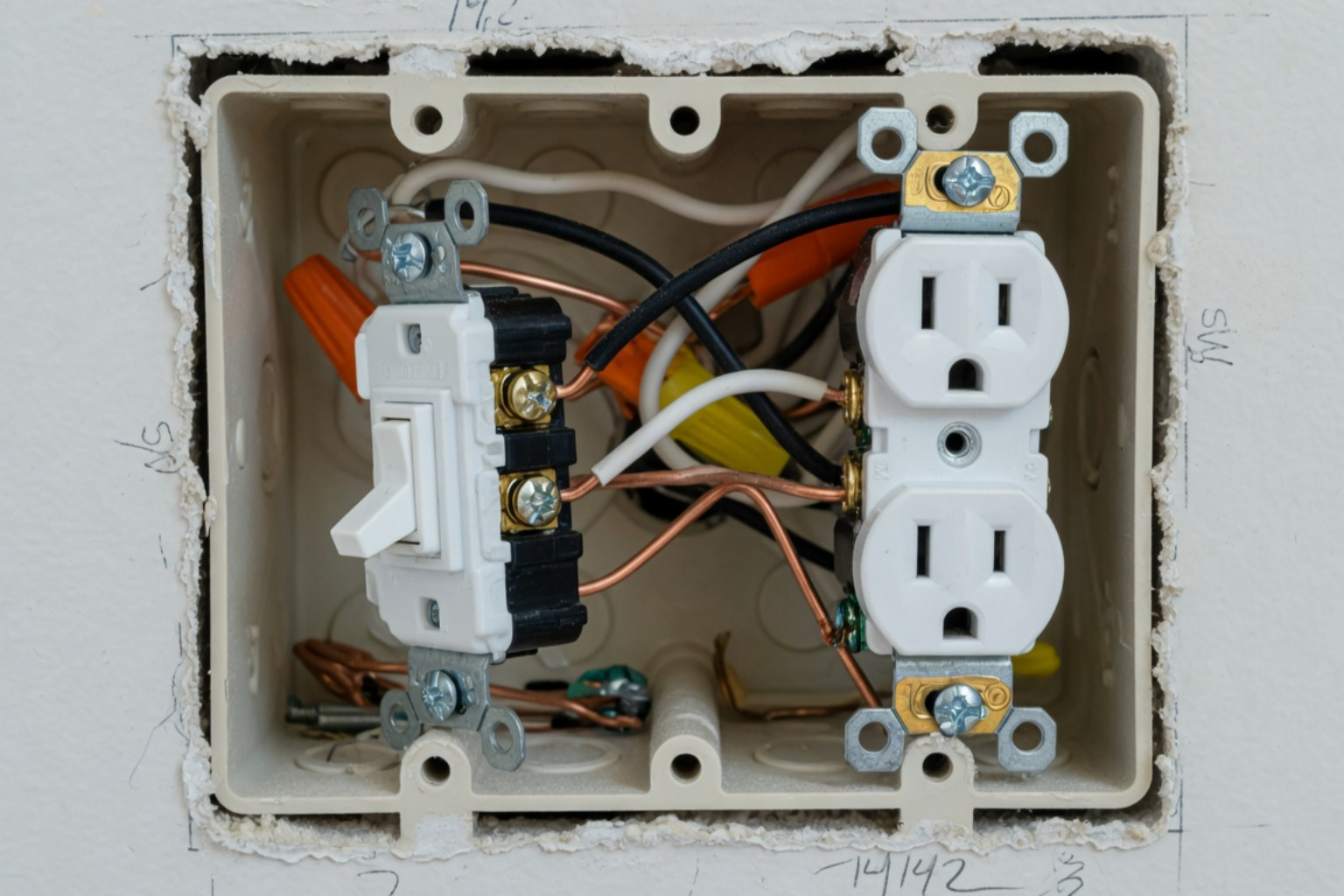
Installing a standard 120-volt duplex receptacle involves attaching the black hot conductor to the brass terminal screw and the white neutral conductor to the silver terminal screw. Always wrap the bare copper ground wire onto the green hexagonal grounding screw.
Avoid using the quick push-in back-wire holes found on the back of many builder-grade receptacles. Over time, these spring-loaded internal clips loosen from thermal expansion, creating high electrical resistance and overheating. Always wrap conductors directly around the side screw terminals or use screw-clamped back terminals.
Single-pole wall switches control power along the hot conductor only. Connect the incoming hot feed wire to one brass terminal screw and the outgoing hot wire leading to the light fixture to the second brass terminal screw. The neutral return wires simply pass through the box connected together with a wire nut.
Multi-Location Control: Three-Way and Four-Way Switches
Controlling a single light fixture from two separate wall locations requires three-way switches. Controlling that same light from three or more locations requires four-way switches installed between the three-way switches.

Three-way switches feature three active screw terminals: one dark-colored “common” screw and two lighter-colored “traveler” screws.
- On the first three-way switch, attach the continuous incoming hot feed directly to the dark common terminal screw.
- Run 3-wire NM cable (which contains black, red, white, and bare ground conductors) between the two switch boxes.
- Connect the black and red conductors to the two lighter traveler screws on both switches.
- On the second three-way switch, attach the dark common terminal screw directly to the black hot wire leading to the light fixture.
- To add a third control point, place a four-way switch in the middle of the run, connecting the traveler pairs from each three-way switch to the four-way switch’s paired line terminals.
Wiring Dedicated 120/240-Volt Appliance Circuits
Heavy-draw household equipment requires dedicated 240-volt appliance circuits wired directly from the main panel to prevent circuit overloads.
- Electric Clothes Dryers: Require a dedicated 30-amp, 120/240-volt circuit wired with 10-3 NM-B copper cable (two hot wires, one neutral, and one ground) connected to a 4-prong NEMA 14-30R receptacle.
- Electric Cooking Ranges: Require a dedicated 40-amp or 50-amp, 120/240-volt circuit wired with heavy 8-gauge or 6-gauge copper conductors terminating at a 4-prong NEMA 14-50R outlet.
Modern installations use four-wire appliance hookups to completely separate the neutral return conductor from the equipment grounding path. Older three-prong cords bonded the appliance’s metal frame directly to the neutral wire, which creates shock hazards if the neutral line ever breaks.
Rough-In Installation, Placement Guidelines, and Troubleshooting
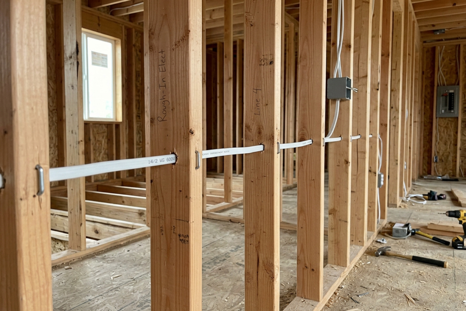
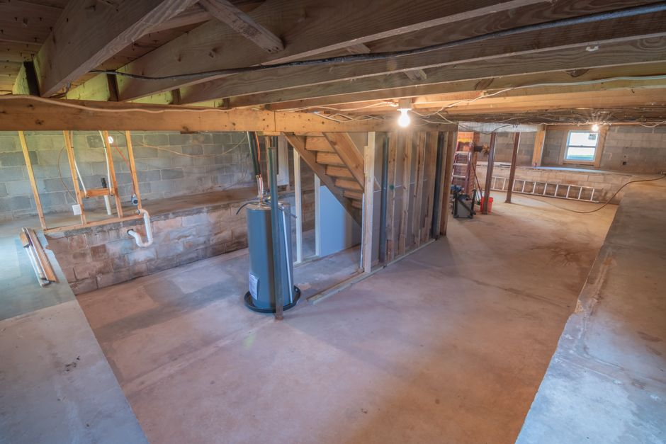
Installing electrical cable inside unfinished framing requires following strict building standards. When completing residential build-outs and remodel wiring, cables must be protected from physical damage behind finished drywall.
When drilling holes through wood studs, bore holes at least 1-1/4 inches away from the nearest framing edge. If a hole sits closer than 1-1/4 inches to the front edge of the stud, we always install a heavy-gauge steel nail protector plate over the face of the stud. This prevents drywall screws from penetrating live electrical wiring.
Support all NM cables by securing them with approved plastic staples within 8 inches of entering an electrical box and at maximum intervals of 4-1/2 feet along framing runs. Review our guide on new construction wiring practices to understand framing clearances in detail.
Standard Height and Spacing Guidelines for Outlets and Switches
Consistent placement standards make home electrical systems convenient and safe:
- General Wall Receptacles: Mounted vertically with box centers standard at 12 inches above the finished floor.
- Wall Switches: Positioned with box centers mounted 48 inches above the finished floor near room entryways.
- The 6/12 Receptacle Spacing Rule: In general living spaces, no point along a floor wall line can be more than 6 feet from an electrical receptacle. This means outlets are spaced roughly every 12 feet along continuous walls so standard appliance cords can reach without extension cords.
- Kitchen Countertops: Receptacles must be placed so that no point along the countertop wall line is more than 24 inches from an outlet. All kitchen countertop outlets require GFCI and AFCI protection.
- Bathrooms: Require a dedicated 20-amp branch circuit powering GFCI-protected outlets placed within 36 inches of the outside edge of each sink basin.
Safe Electrical Troubleshooting and Short Circuit Diagnosis
When an electrical circuit suddenly loses power, identify whether the issue is an overload or a short circuit before resetting the breaker:
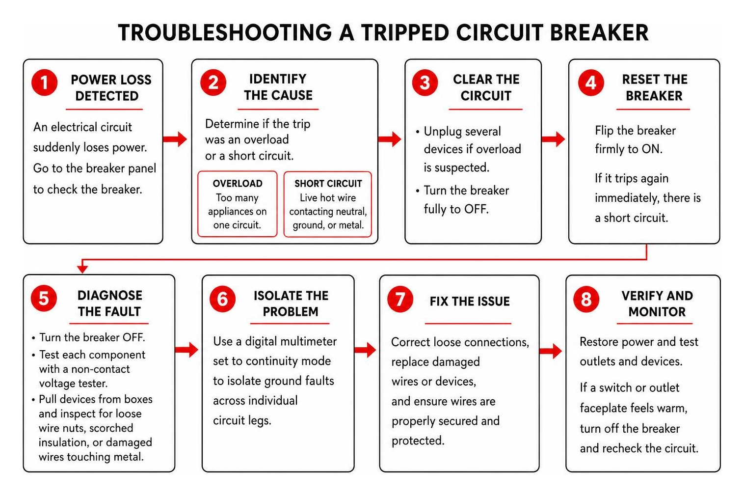
- Circuit Overload: Occurs when too many appliances operate simultaneously on one circuit, exceeding its safe continuous capacity (1,500 watts for a 15-amp circuit, 2,000 watts for a 20-amp circuit). Unplug several devices and reset the breaker fully to the OFF position before flipping it back ON.
- Short Circuit: Occurs when a live hot conductor contacts a neutral wire, ground wire, or bare metal enclosure, causing instant high current flow that immediately trips the breaker.
- Diagnosing the Fault: Turn the breaker off and test each component with a non-contact voltage tester. Pull devices out from their boxes to inspect for loose wire nuts, scorched insulation, or damaged wire jackets touching metal boxes. Use a digital multimeter set to continuity mode to isolate ground faults across individual circuit legs.
- Warm Faceplates: If a switch or outlet faceplate feels noticeably warm to the touch, turn off the controlling circuit breaker immediately. Warmth points to a failing device, an overloaded branch circuit, or high-resistance loose connections inside the wall.
Frequently Asked Questions About Home Wiring Manuals
What are the most important safety steps before starting any home electrical project?
Always shut off power to the target circuit at the main service panel, and switch off the main disconnect if you are unsure which breaker controls the circuit. Use physical lockout/tagout methods by taping the breaker in the OFF position and posting a warning sign on the panel door. Before handling any conductor, insert an audible, touch-free voltage tester directly into the work area and test every single wire to confirm that no live current is present.
How do I know whether my project requires 14-gauge or 12-gauge wire?
Match wire gauge directly to the circuit breaker’s rated amperage:
- 14 AWG Copper Wire: Exclusively used for 15-amp branch circuits (maximum continuous load capacity of 1,500 watts).
- 12 AWG Copper Wire: Required for all 20-amp branch circuits (maximum continuous load capacity of 2,000 watts).
Never connect thinner 14-gauge wire to a 20-amp circuit breaker, as the wire can overheat and create a fire hazard before the 20-amp breaker trips.
When does a DIY wiring project legally require a permit and professional inspection?
Minor like-for-like repairs—such as swapping a standard switch, replacing an existing outlet, or changing a light fixture—generally do not require building permits.
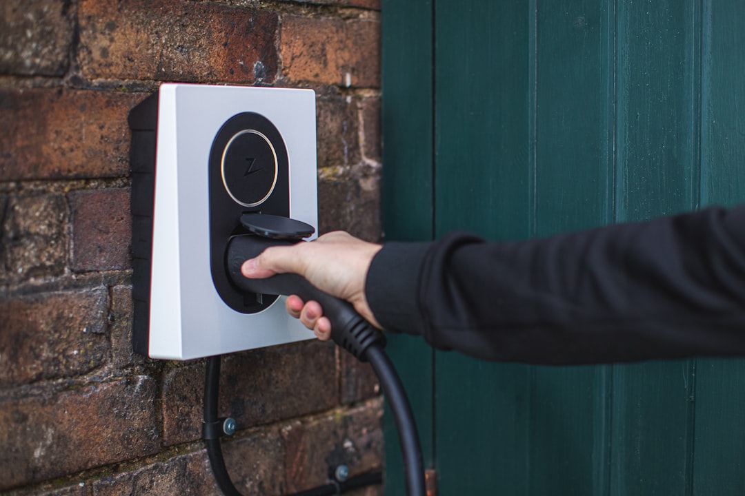
However, running new branch circuits through walls, installing subpanels, upgrading the main service panel, rewiring rooms during remodels, or adding high-voltage 240V circuits for appliances and EV chargers require municipal electrical permits and formal inspections by local building authorities.
Conclusion
A well-illustrated home wiring guide is a great way to understand how power moves through your walls. But there is a clear line between replacing a worn light switch and taking on extensive panel work, whole-home rewiring, or running heavy 240-volt appliance feeds.
What I usually see in Denver homes—especially properties that are several decades old—is a mix of past DIY work, crowded electrical boxes, and circuits carrying more load than they were originally designed for. When you run into confusing layouts, flickering lines, or projects that require pulling permits, having a master electrician handle the heavy lifting keeps your home safe and fully up to code.
If you are planning an extensive electrical upgrade or need assistance with your home’s wiring, reach out to our team for reliable professional residential electrical services. We will make sure your home’s power runs safely, efficiently, and trouble-free.